
fast, traceable and secure delivery
prices dedicated to professionals and resellers
technical support and professional advice
financing and installment payments
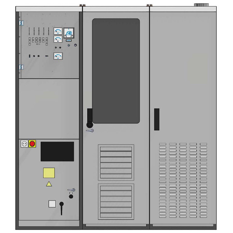
TRAM50
Elsycom
50 kW Solid State MF Broadcast Transmitter
Amplifier
The amplifier section of the transmitter has one 50 kW power block equipped with 48 power modules. This power
module is the basic unit of the RF amplifier. It supplies somewhat more than 1 kW into a special series transformer
assembly (doughnut combiner) which summarises the power of all 48 power modules to the total transmitter power of
50 kW.
The module is designed as one single printed circuit board, which is plugged into the assembly. The module comprises
a switched RF amplifier bridge and an associated PDM modulator. Each unit supplies a completely modulated RF
signal into the combining transformer. Thus in case of a module fault the service is maintained with only slightly reduced
power but without reduction of quality performance.
RF Output Filter
The 50 kW power block has an RF output filter which is contained in one 19" cabinet.
The transmitter is factory equipped for and tuned on the determined operation frequency. The coils of the output circuit
can be tuned for the whole MF band, while the capacitors are determined for sub-ranges of this frequency band.
Drive and Signal Processing
The transmitter is equipped with a common drive unit (PLL synthesizer) and a common PDM processing unit for all
power modules. A dual synthesizer assembly in passive standby configuration is available as an option. The RF drive
can also be switched to an external frequency generator or synchronised from an external standard.
Power Supply
A common power supply, comprising a 400 V to 210 V three-phase transformer and two three-phase rectifier units, is
provided for the 50kW power block. Each rectifier unit is fed from an independent phase-shifted 210 V transformer
output. This feeding provides 12-pulse ripple, only. The 400 V / 230 V feed also supplies the auxiliary equipment.
In the standard configuration, the transformer is contained in the bottom of the amplifier cabinet. As an option, we also
provide a solution where the transformer is located externally from the transmitter.
Cooling
The components of the whole transmitter are basically air-cooled. A fan assembly located below the 50 kW power block
moves the cooling air along the heat sinks of the power modules. This fan assembly compensates only the pressure
drop inside the amplifier cabinet. The air is taken from the room and will be exhausted into the room.
Should external air ducts be required, an additional external blower system is needed to compensate the pressure drop
in the external air ducts. Layout of the external air cooling system depends on the individual conditions at site.
Control Section
The control section of the transmitterc omprises the 400 V / 230 V mains input, the internal distribution, the control
panel with the components for local control and for metering as well as the remote-control interface. Furthermore, it
comprises the common drive unit (PLL synthesizer) and the AF input unit with PDM processing
Amplifier configuration 50 kW power block, equipped with 48 individual power modules. Each power module comprises an RF amplifier and an envelope modulator. One further power module of the same type is employed as driver module for the 50 kW power block.
RF output power:
° 50 kW carrier power
° Typical > 40 kW DRM power with external DRM Exciter
RF power reduction : Two preset power levels P1 and P2 - (P1 adjustable from 50% to 100%, P2 adjustable from 25% to 50%)
Frequency range 525 kHz to 1710 kHz - The TX will be equipped for and tuned on the determined operation frequency in factory (components for other frequencies on request)
Frequency stability Deviation < +/- 2 ppm under operating conditions - Input for external synchronization (selectable 1 / 2 / 5 / 10 MHz)
Operation modes:
° AM (A3E)
° DCC mode DAM (X3E) or AMC / EAMC (selectable by jumper setting)
° DRM with external TRANSRADIO DRM Exciter
RF output connector : 3-1/8" EIA
Load impedance : 50 Ohm unbalanced
Load VSWR :
Power supply : 3N 400 V, TN-S resp. TN-C mains configuration (5-wire resp. 4-wire)
Mains frequency : 50 Hz (60 Hz on request)
Permissible voltage variation :
° ± 5% with full performance
° ± 10% with minor performance degradation
Power factor > = 0.95
Power consumption : > 57.5 kW at no modulation - >86.2 kW at 100% modulation
Overall efficiency : > 87%
Environmental temperature : - 10° C … + 45° C
Relative humidity : Max. 90% (non-condensing)
Installation altitude : Max. 2000 m above sea level (higher altitudes on request)
Cooling system : Air cooling with internal fan assembly below the power block (air intake from the room, exhaust air into the room)
Cooling air consumption : approx. 3300 cbm / h - External blower system with filtering and air ducts on request
Dimensions : WDH = 1800 mm x 1000 mm x 2000 mm
1x Amplifier cabinet
1x Filter cabinet
1x Control cabinet
Other products in the same category